In this section, we fix ![]() and investigate the behavior of
system limit cycles.
and investigate the behavior of
system limit cycles.
We use the Poincare mapping method to investigate the properties
of periodic solutions of Eq. (7). We take an
appropriate local plane as the Poincare section, for instance,
![]() or
or ![]() , and then calculate the bifurcation
parameter values by using the Poincare map and its derivatives.
, and then calculate the bifurcation
parameter values by using the Poincare map and its derivatives.
There are three kinds of local bifurcations for periodic solutions in this system:
Figure 2 shows a bifurcation diagram in the ![]() -
-![]() plane for periodic solutions. In this figure, roughly speaking,
there exist three divisions in the plane. Each region has stable
attractors, i.e., sinks (
plane for periodic solutions. In this figure, roughly speaking,
there exist three divisions in the plane. Each region has stable
attractors, i.e., sinks (![]() and
and ![]() ), chaos, and limit
cycles. Many islands (windows) giving periodic solutions are embedded in the
chaotic region. Each island is basically composed of a set of
bifurcation curves (T, Pf, Pd), as illustrated by
Fig. 3.
), chaos, and limit
cycles. Many islands (windows) giving periodic solutions are embedded in the
chaotic region. Each island is basically composed of a set of
bifurcation curves (T, Pf, Pd), as illustrated by
Fig. 3.
 |
Figure 4 shows an enlargement of Fig. 2.
Let us first observe the responses of the system when the parameter
![]() changes gradually from the lower part to the upper part along
the line
changes gradually from the lower part to the upper part along
the line
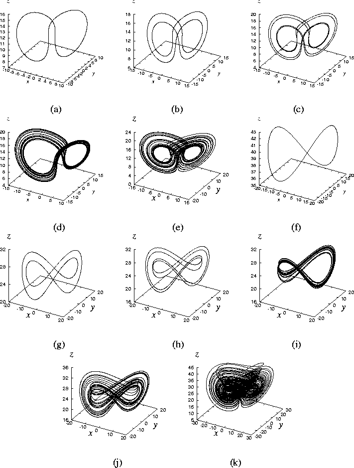
![]() . The periodic solution, shown in
Fig.5 (a), is generated by the tangent bifurcation T
via intermittent chaos. This solution is divided into two stable
limit cycles after crossing the pitchfork bifurcation Pf, see Fig
5 (b). They form the Lorenz-linkage [Jackson, 1991].
Let
. The periodic solution, shown in
Fig.5 (a), is generated by the tangent bifurcation T
via intermittent chaos. This solution is divided into two stable
limit cycles after crossing the pitchfork bifurcation Pf, see Fig
5 (b). They form the Lorenz-linkage [Jackson, 1991].
Let
![]() be a solution of
this system with initial condition
be a solution of
this system with initial condition
![]() . Let
. Let
![]() and
and
![]() be the limit cycles generated by Pf. The relationship between these
two cycles is as follows:
be the limit cycles generated by Pf. The relationship between these
two cycles is as follows:
On the other hand, by changing parameter ![]() along the line
along the line
![]() , Figs. 5 (f)-(k) are obtained,
which show the corresponding phase portraits. We can see the same
bifurcation scenario. However, the chaotic attractor shown in Fig.
5 (k) is somewhat different from a Lorenz-type attractor
by means of its spiral shape over the two screws, which does not
have the tendency to move to any two-dimensional surface.
We further discuss this attractor in Sec.3.4.
, Figs. 5 (f)-(k) are obtained,
which show the corresponding phase portraits. We can see the same
bifurcation scenario. However, the chaotic attractor shown in Fig.
5 (k) is somewhat different from a Lorenz-type attractor
by means of its spiral shape over the two screws, which does not
have the tendency to move to any two-dimensional surface.
We further discuss this attractor in Sec.3.4.
Figure 6 shows bifurcation curves that form another island. Figures 7 (a)-(d) are phase portraits observed on the parameter sets a-d indicated in Fig. 6. Also, the same bifurcation scenario can be observed.
Figure 10 is also an enlargement of the upper part of
Fig. 2, showing regions sectioned by
bifurcation curves. In each region,
there exists at least one topologically different stable attractor
against another region. The tangent bifurcation curve T for a limit
cycle is coalesced by the pitchfork bifurcation curve Pf. Thus,
two periodic orbit generated by Pf is immediately disappeared by T
at the boundary of (A) and (F).
In region (F), we have a chaotic attractor as shown in
Fig. 8. This attractor is probably related
to a kind of homoclinic orbits about ![]() , since some parts of the orbit are
tangent to the plane including unstable manifolds of
, since some parts of the orbit are
tangent to the plane including unstable manifolds of ![]() ,
as can be seen from Fig. 8 (a)-(d). This
chaotic orbit changes its shape to be Lorenz-like, when the
parameter is changed toward inside of region (F). This can be seen
from Fig. 11. Further investigation of this
orbit is very interesting but time-consuming, which will be
summarized and presented in a future article. As the parameter
set is changed from region (B) toward region (C), the limit cycle
meets the period-doubling cascade diagram started from Pd. In
region (C), there also exist chaotic solutions.
,
as can be seen from Fig. 8 (a)-(d). This
chaotic orbit changes its shape to be Lorenz-like, when the
parameter is changed toward inside of region (F). This can be seen
from Fig. 11. Further investigation of this
orbit is very interesting but time-consuming, which will be
summarized and presented in a future article. As the parameter
set is changed from region (B) toward region (C), the limit cycle
meets the period-doubling cascade diagram started from Pd. In
region (C), there also exist chaotic solutions.
 |
The island composed of regions (D) and (E) showing periodic motions
connects to region (B). Figures 9 show the
corresponding Lyapunov exponents along ![]() from (A) to (F). From
these exponents, it is seen that there exists a very narrow area
exhibiting chaos between (C) and (D).
from (A) to (F). From
these exponents, it is seen that there exists a very narrow area
exhibiting chaos between (C) and (D).
In Fig. 10, the curve H shows Hopf bifurcation for
![]() described by Eq. (16). There is no
stable periodic solution in region (I), and there exist two stable
limit cycles in region (G). In fact, there also exist two unstable
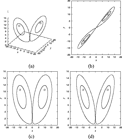
(saddle-type) limit cycles in this region. Figure 12
shows these limit cycles and the unstable equilibria. These two
cycles disappear when reaching the tangent bifurcation T. After
this bifurcation, one can see a chaotic attractor as shown in Fig.
11. Note that this chaotic attractor can survive
in regin (I); in other words, coexistence of stable equilibria and
chaotic attractor occurs in region (I).
described by Eq. (16). There is no
stable periodic solution in region (I), and there exist two stable
limit cycles in region (G). In fact, there also exist two unstable
(saddle-type) limit cycles in this region. Figure 12
shows these limit cycles and the unstable equilibria. These two
cycles disappear when reaching the tangent bifurcation T. After
this bifurcation, one can see a chaotic attractor as shown in Fig.
11. Note that this chaotic attractor can survive
in regin (I); in other words, coexistence of stable equilibria and
chaotic attractor occurs in region (I).
 |